
FIRST STEP
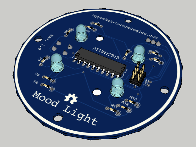
One of my first projects I wanted to try was a mood light. I’ve seen a number of these on the internet, so I thought I would try my hand at one. Ok, I know its not the most difficult project, but baby steps. The first thing I did was design my board. It tooks me a week or so to design it, and get all the connections correct, but this is what I ended up with.
 |
 |
During the time the board was sent away being created. I discovered sketchup. If you don’t know about this app, get to know it. It’s GREAT! It took me about 3 days to get proficient with it but once I did I was on my way. Once I modeled my board in 3D, I realized that I did a few things wrong. I had tried to plan out how I would mount the board and I even thought about the final package design. But with out modeling it in 3D It’s really difficult to think of every detail.
 |
 |
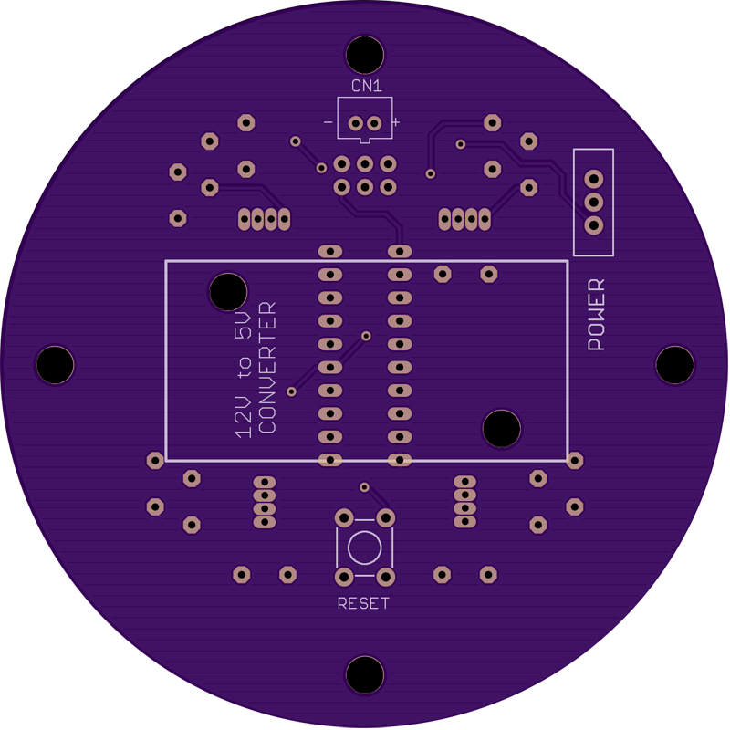
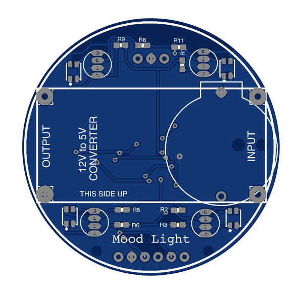
One of the things i didn’t really think through was how I would plug it in. I knew that I needed to convert 12V to 5V so I added the power converter on the bottom. However, I forgot the plug. I could get one in there but it would probably be a hack. The other thing I did was make the board WAY to big. Due to the size it was a little to expensive to fix the minor issues with this board. Live and learn I guess.
After I got the boards back from the PCB manufacture I realized I had a few errors. For starters I wired the slide switch wrong, oops. Then I found that one of the lights would flicker and stutter. All the other lights worked just fine. I fixed the errors but I was disappointed.
NEXT STEPS (REDESIGN)
After seeing the mistakes of my first board, I got back on eagle CAD and started making a new version. For starters I made the board 1/2 the size of the original. This will keep the cost down and If I need to have them reprinted I should be able to afford to do so. In order to make my board smaller I decided to use SMD (Surface Mount Device) / SMT (Surface Mount Technology) components. I’ve done a little SMD soldering but not as much as this board will demand ;-/
|
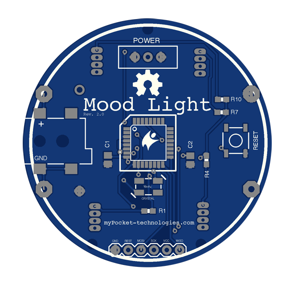 |
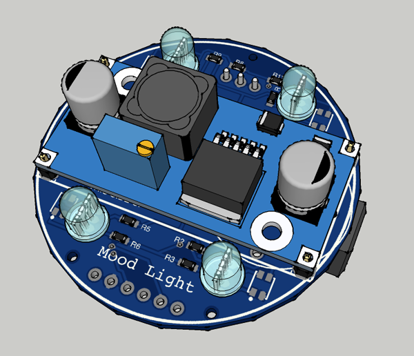
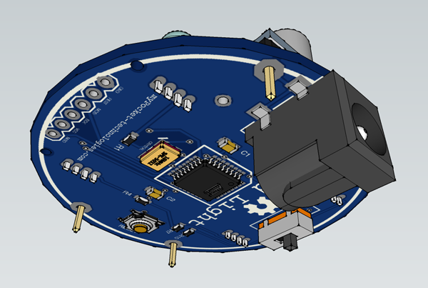
I decided to make this with 2 types of lights. DIP RGB LED’s and surface mount RGB LED’s. The board should be able to use either one depending on what components I might want to use. I also decided to use a different microprocessor. My original design utilized a ATTiny 2313 but this new board required something smaller. So I found a great deal on ebay for some ATMega88A devices in a TQFP package. I also added the ability to add a battery pack to the board instead of attaching a power converter. I thought this might be an interesting addition. I might not even use it, but It’s easier to add now than later.
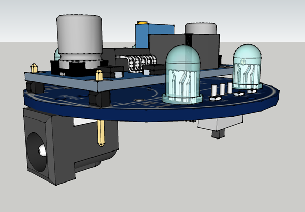
This time I modeled my boards with greater detail. I wanted to make sure that all my components will fit with no modifications. I found a way to mount the power converter directly to my custom board, and used a surface mount DC barrel jack to my board.
 |
 |
 |
|
WAITING FOR COMPONENTS
Im still waiting for my SMD/SMT RGB LED’s so in the mean time I will be working on the final design of the rest of the light.